Reverse engineering an Ecoteck wood pellet stove remote control

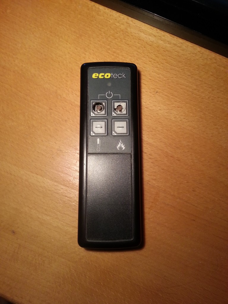
In our living room we have an “Ecoteck Francesca” wood pellet stove that helps us keep a reasonable temperature during winter. The problem is, however, that the remote control is horribly bad (yes, it has a friggin’ remote control). At this point I have already had to replace the buttons in it once, as the old ones were beginning to wear out.

Ecoteck remote control

Ecoteck remote control

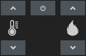
There are four buttons. Two for adjusting the target air temperature and two for adjusting the level of flames or something. Pressing the two uppermost buttons at once turns the stove on or off. I haven’t looked at other Ecoteck models, but the codes in this post may also work for other models that has the same control electronics. The front panel looks like this:

Ecoteck Francesca front panel

Ecoteck Francesca front panel

So, for the long run we might have to find some sort of replacement of this remote control. Fortunately, our Samsung tablet has an IR transmitter on-board that would be perfect for this. There’s even an easy to use Android API for accessing it. The problem is then that the tablet has no built-in way of “recording” the IR signal from the old remote. And the protocol is nowhere to be found online (until now, that is). So before we can create an Android app, we need to get the codes and modulation settings from the old remote control.

How to get the codes

One approach would be to get the USB Infrared Toy from Seeed and record the transmitted codes directly, but instead I decided to try out a simple logic analyzer I just received in the post from China. It’s not really a logic analyzer per se, but rather a breakout board for the Cypress CY7C68013A MCU, which is the same chip as the one in the original Saleae Logic. It even enumerates as a Saleae device when I plug it in. So, basically it’s a knockoff. Naughty Chinese!

However, word on the interwebs has it that it won’t work with recent versions of the Saleae Logic software due to some minor hardware differences regarding the onboard EEPROM chip. But all this doesn’t matter, as I’ll be using the open source PulseView tool from the sigrok project instead.

Getting the codes

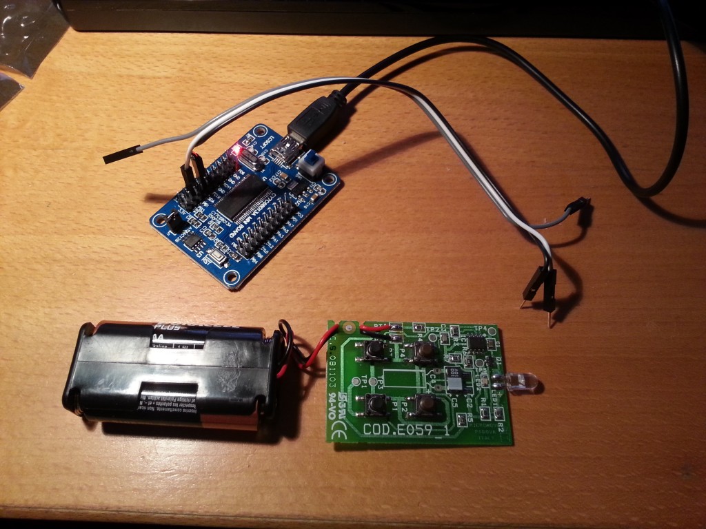
It’s not necessary to build a fancy IR receiver. Just open the remote control and attach a couple of probes across the IR LED. The voltage drop here is big enough to trigger the logic analyzer. I started the analysis by having a look at the signal itself by sampling at 24 MHz and pressing a button.

The setup

The setup

The signal consists of a series of infrared pulses, which seems to be grouped into blocks. An “on-block” is 30 pulses long. An “off-block” has no pulses, but lasts for the same duration as an “on-block”. Each individual pulse is on for 8.25 μs and off for 19.625 μs except for the last cycle of each block which is only on for 5.25 μs. The interval between the last pulse of a block and the first pulse of the next block is 28.5 μs.

29 pulses, 1 end-of-block pulse, and the beginning of the next block.

29 pulses, 1 end-of-block pulse, and the beginning of the next block.

Thus a normal pulse is 27.875 μs long, which means a modulation frequency of 35874 Hz. I don’t know if the duty-cycle matters at all. Time will tell… The length of a block (incl the inter-block distance) is then: 29 * 27.875 μs + 5.25 μs + 28.5 μs = 842.125 μs.

Now that we have the signal timings we can zoom out a bit. For the rest of the analysis a lower sampling rate is sufficient. In the following 1 means a high block and 0 means a low block.

A single button press

A single button press

Notice how the slight inter-block delay causes the anti-aliasing to color each block a slightly different shade of gray. If we annotate the trace with 1s for on-blocks and 0s for off-blocks, we get something like this:

Annotated button press

Annotated button press

If we do this for all 5 functions, we get these codes:

Ecoteck remote control codes

FunctionCode
Temperature up111111110001111001010011011010100110101011
Temperature down111111110001111001010011110010100111110011
Fire up111111110001111001010011111010100111101011
Fire down111111110001111001010011101010100111001011
On/off111111110001111001010011010010100110110011

Now we have all the necessary data we need to create a compatible remote control.

Implementing an Android app

Based on these codes, I have made a simple Android widget that should work on any phone/tablet that has an IR transmitter and runs Android 4.4.2 (API level 19). It relies on the ConsumerIrManager class that was added in that release.

During normal operation the widget looks like this:

Ecoteck widget

Ecoteck widget

To prevent turning the stove on or off at a bad time, I originally intended the power button to be activated only if the user pressed and held it. However, in Android the long press event is reserved for doing widget management stuff and cannot be used by the widgets themselves. Bummer… Instead the widget presents the user with a confirmation dialog of sorts if the power button is pressed:

Confirm on/off command

Confirm on/off command

I have been using the widget exclusively for a couple of days now and it works like a charm. 🙂

That’s it!

As usual, all code for this project can be found on GitHub. If you have any questions, please comment below.
Creating a python module for the Contec CMS50D+ pulse oximeter (Part II)

So, in my previous post, I wrote a bit about retrieving live 60 Hz data from a Contec CMS50D+ pulse oximeter. As mentioned, the device also has another standalone mode where it records pulse rate and blood SpO2 at 1 Hz for up to 24 hours. That is, if your batteries last that long. This thing is quite power hungry.

You can read all about the recording mode in the manual. In this post I’ll focus on the actual data download from the device. There’s really not much to it, so it will be a short post this time…

Let’s look at some recorded data

Whereas the live-mode is strictly one-way, the recorded mode involves a tiny bit of two-way communication to work. You should enable xonxoff to convince Python to talk to the device. The protocol goes as follows:

  • Open a connection at 19200 baud, 1O8 with xonxoff enabled.
  • Listen for live data. If we get none, the device is disconnected or turned off.
  • Send [0xF5, 0xF5]. This switches the device to download mode.
  • Wait for the preamble. It’s three times [0xF2, 0x80, 0x00]. In the beginning we might also have some leftover live data.
  • Then we get the content length as three bytes. See below for an explanation.
  • Receive the specified number of bytes. Each measurement is three bytes. See below for an explanation. Sometimes the download fails and halts midway for some reason and has to be restarted.
  • Send [0xF6, 0xF6, 0xF6]. This switches the device back into live mode.
  • Disconnect.

Now you should have a bunch of data to insert into a spreadsheet or whatever.

The length header

The length header tells us how many bytes of data the device will send. It consists of three bytes. The first two bytes always have their MSB set while it’s never set on the last. This gives us 21 useful bits which is enough. If we have recorded 24 hours of data, this will yield 24 * 60 * 60 = 86400 measurements. And if each measurement is three bytes, then the maximum content length will be 259200 bytes. This only requires 18 bits.

Curiously enough, the content length is always one off compared to the actual data length. So we need to add 1 to the result. Let’s look at an example:

  • We have received the length header [0x81, 0x8A, 0x2C].
  • Validate and strip off MSBs from the first and second byte. Now we have [0x01, 0x0A, 0x2C].
  • Left-shift the first byte by 14 bits and the second byte by 7 bits. Combine the three numbers by using the bitwise OR operator. Now we have 0x452C or 17708 in decimal.
  • Add 1 to the result. This means that the content length is 17709 bytes.
  • Each measurement is three bytes, so we have 17709 / 3 = 5903 measurements. As the device samples at 1 Hz, this means 1 hour 38 minutes and 23 seconds worth of data.

The measurements

Each measurement consists of three bytes.

  • The first byte is always 0xF0 or 0xF1. The 1 is the MSB of the pulse rate in the next byte.
  • The second byte is the pulse rate. As the device only utilizes 7 bits per byte for data, the MSB is moved to the first byte. A human pulse rate can quite easily go over 127 BPM…
  • The third byte is the SpO2 percentage.

That’s it!

Again, all code for this project can be found on GitHub. If you have any questions, please comment below.
Creating a python module for the Contec CMS50D+ pulse oximeter (Part I)

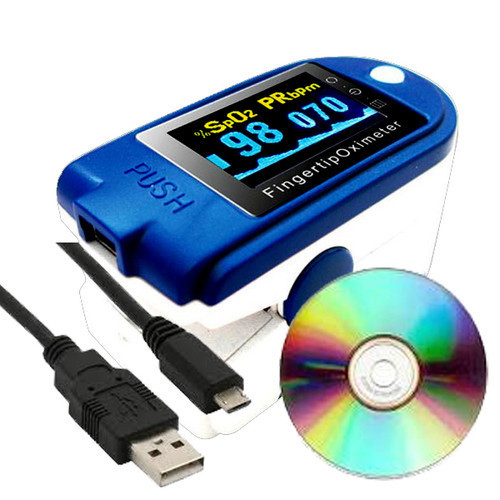
Some time ago I wrote a bit about how to download data from a Beurer BM65 blood pressure monitor to my PC via USB using a homemade Python module. That was good fun, so when I discovered the Contec CMS50D+ pulse oximeter (which also has USB connectivity) on everybody’s favorite online auctioning site for ~$40 including shipping, I had to buy one.

Contec CMS50D+

Contec CMS50D+

So, what’s in the box?

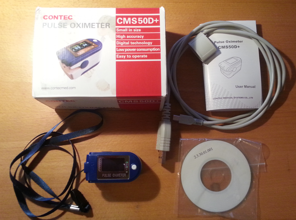
Apart from the device itself, the box contains a special USB cable (we’ll get back to this), a lanyard (because why not), no batteries, a small mysterious CD-ROM, and a surprisingly well-written English instruction manual. The device works as expected and outputs plausible data on it’s little display, which is very crisp by the way. I can’t vouch for the validity of the blood oxidation level, but the pulse stuff seems pretty precise at least. However, this is not the important part of this blog entry. Let’s focus on getting data off the damn thing without having to rely on the official software.

Contec CMS50D+ box content

Contec CMS50D+ box content

Plugging it in

Others have already reverse engineered the protocol of this device, but let’s have a look at the bundled software anyway. After updating all the anti-malware software on my Windows box, I tried putting in the CD-ROM. So far it seems benign enough. It contains a single executable that installs a driver and two applications: one for live data display and one for downloading up to 24 hours of recorded data from the device. The software isn’t actually half bad, but as usual it’s unfortunately Windows-only. It runs in Wine, but sadly fails to connect to the device.

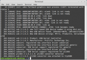
The bundled driver is for the Silicon Labs CP210x series of USB to UART converters, which simplifies things considerably. Now it’s just a matter of sniffing some serial traffic. In Linux, dmesg agrees with this when the device is plugged in:

CP2102 detected!

CP2102 detected!

Fun fact: The CP2102 chip is also detected if I only plug in the bundled USB cable and leave the pulse oximeter itself disconnected. Apparently this cable has a built-in USB to UART converter! That’s a bit weird considering the mini-USB plug at the other end… Even though the device itself sports a mini-USB connector, it’s not actually USB compliant and it won’t work at all with regular USB cables. So don’t throw away the special “USB cable”!

Let’s look at some real-time data

The device has two modes: real-time data and recorded data (up to 24 hours). The former streams data via the USB connection as it’s measured, while the latter is useful for situations where a running PC would be impractical. The real-time mode offers relatively rich 60Hz data while the historical mode only supports 1Hz averaged pulse and Spo2 readings. Coding-wise the real-time mode is the simplest as its protocol is one-way, so it’s a good place to start. I’ll cover the recorded data mode in another post.

Anyway, I tried starting the live data application through API Monitor v2 like I did for the blood pressure monitor. Immediately when the live data application starts, it starts spamming the SetCommState API call in Kernel32.dll trying to open all available COM ports at 4800, 19200, and 115200 baud in quick succession. All three bitrates are configured as 8O1 (oddly enough). Perhaps this is in order to support several slightly different devices?

Another slightly odd thing is that the device is always transmitting data without any handshake. All the computer has to do is to open the right virtual serial port at 19200 baud 8O1. Yet another slightly odd thing is the protocol itself. Each data packet is 5 bytes long and according to some documentation found on the web, 60 packets are sent per second. The first byte always has its MSB set to 1 while the four others always have it set to 0. According to said documentation, the meaning of the 5 bytes are as follows (spelling errors and all):

bytebitcontent
10~3Signal strength for pulsate(0~8)
41=searching too long,0=OK
51=dropping of SpO2,0=OK
61=beep flag
7Synchronization,always be 1
20~6pulse waveform data
7synchronization,always be 0
30~3bar gragh (stand for pulsate case)
41=probe error,0=OK
51=searching,0=OK
6bit 7 for Pulse Rate
7synchronization,always be 0
40~6bit 0~bit 6 for Pulse Rate
7synchronization,always be 0
50~6bit 0~bit 6 for SpO2
7synchronization,always be 0

I think this information is for a slightly different model (hence the 4800 baud setting instead of my device’s 19200 baud), but it seems legit. In any case, I have yet to see data that doesn’t make sense according to this table.

Like last time, I have implemented a small python script that is able to connect to the device. It takes a few command line arguments and outputs a CSV file with the received data.

All code for this project can be found on GitHub.

Next up: Retrieving historical data for the last 24 hours… Stay tuned…

Creating a Python module for the Beurer BM 65 blood pressure monitor (Part I)

So, I just bought a brand spanking new blood pressure monitor. My wife is a nurse and we have been talking about getting one for some time. After browsing the market, we settled on a Beurer BM 65. It is a very nice piece of kit and it comes with a USB plug for PC connectivity. Exciting, right? Unfortunately, the software is Windows-only. Bummer..

Beurer BM 65

Beurer BM 65

Well, then it’s obviously my duty to reverse-engineer it. Let’s get started then! A quick Google search tells me that others have had success with the Beurer PM70 (a heart rate monitor) and success with the Beurer BG64 (a diagnostic scale). They seem to use different protocols, though.

Reverse engineering the protocol

When the BM 65 is plugged in, it enumerates as 067B:2303, which is a Prolific Technology PL-2303 USB-to-serial controller. Interesting.. The problem is therefore reduced to guessing the serial protocol it uses.

Output from dmesg

Output from dmesg

On my Linux box it gets mapped to /dev/ttyUSB0 with no issues, as this chip is supported in the kernel. But how to communicate with it? We need to sniff the protocol… Beurer provides a free Windows-only tool called Health Manager for communicating with the device, as well as a subset of their other products. Luckily, it’s possible to eavesdrop on serial ports in Windows, and my gaming rig runs Windows 7. There is a SysInternals tool for this called Portmon, but it seems to work very poorly on Win7 x64. Next, I tried a tool called API Monitor v2. As the communication with the device is through a fake serial port, we should be able to sniff the relevant Windows API calls.

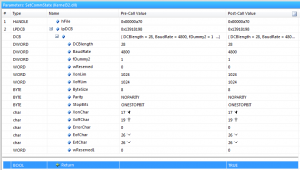
Lo and behold! It works! It seems that SetCommState in Kernel32.dll is used to configure the COM port (4800 baud 8N1).

4800baud

The SetCommState call where the serial connection is set up to 4800 baud 8N1.

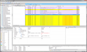
Let’s then see if we can deduce the actual communication.. After some digging around I successfully limited the captured API calls to just the file I/O stuff in Kernel32.dll. The Health Manager tool tries all available COM ports until it gets a correct response. After that, we just have to follow the yellow brick road of WriteFile and ReadFile API calls. It only writes 1 or 2 bytes per call (depending on the command) and all reads are single byte reads.

Serial data transfer

Serial data transfer

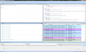
This API Monitor tool is a bit tedious for this, so I tried Serial Port Monitor by Eltima Software instead. It is a shareware program with a 14 day trial, but that’s enough for this purpose. A serial dump of a sequence of 3 measurements looks something like this:

Captured serial communication

Captured serial communication

In table form, transferring a set of three measurements goes like this:

Sent to deviceReceived from deviceMy interpretation
0xAAPing?
0x55Pong!
0xA4Get description
"Andon Blood Pressure Meter KD001"Device description
0xA2How many measurements?
0x033 measurements!
0xA3 0x01Get measurement 1
0xAC 0x66 0x37 0x4E 0x0A 0x11 0x16 0x2A 0x0DMeasurement 1!
0xA3 0x02Get measurement 2
0xAC 0x62 0x35 0x5F 0x0A 0x0E 0x12 0x0C 0x0DMeasurement 2!
0xA3 0x03Get measurement 3
0xAC 0x64 0x3D 0x55 0x0A 0x0C 0x0E 0x09 0x0DMeasurement 3!

After the last byte, the connection is terminated. Apparently, this device is made by a company called Andon. And it seems that it only transmits data about a single user at a time. Let’s have a look at a single measurement:

Byte valueMy interpretationDescription
0xAC0b10101100Status bits? Magic number?
0x66102 + 25 = 127 mmHgSystolic blood pressure (offset by 25)
0x3755 + 25 = 80 mmHgDiastolic blood pressure (offset by 25)
0x4E78 BPMPulse
0x0A10 = OctoberMonth
0x1117Day of month
0x1622Hours
0x2A42Minutes
0x0D13 = 2013Year

And Bob’s your uncle! We have now successfully reverse engineered the protocol. Well.. Almost.. I haven’t got a clue about the first byte of each measurement. It might be a magic number, but it’s probably some status bits. Besides blood pressure and pulse, the device also registers cardiac arrhythmia. If this information is recorded and if a measurement is always 9 bytes, it would have to be stored in these bits.

I mentioned that the device seemed to be made by Andon. After a bit of digging, I found some evidence for this. The document from dabl Educational Trust says:

“Andon is an OEM manufacturer for the BM 65. Despite the different designs, the BM 65 is functionally the same as the Andon KD-5915 with added dual user, averaging and uploading features but without the voiced results.”

It seems that some of the other Andon devices also support USB. I wonder if the protocol is the same as for the BM 65?

Implementing a Python module for the Beurer BM 65

Let’s make a rudimentary data downloader in Python using our newly acquired knowledge about the protocol. I’m using Python 2.7 on a reasonably new Linux Mint installation. The code is reasonably basic, omitting any kind of error handling.

For those who don’t want to copy code from here, you can also pull a copy from GitHub.

Disclaimer:
The code is free to use, but do so at your own risk.
If you brick your device, it’s not my problem.

[code language=”python”]
import sys, serial

class Measurement(object):
def __init__(self, data):
self.header = data[0]
self.systolic = data[1] + 25
self.diastolic = data[2] + 25
self.pulse = data[3]
self.month = data[4]
self.day = data[5]
self.hours = data[6]
self.minutes = data[7]
self.year = data[8] + 2000
self.time = “{0}-{1:02}-{2:02} {3:02}:{4:02}”.format(self.year,
self.month,
self.day,
self.hours,
self.minutes)

def getBytes(self):
return [self.header,
self.systolic – 25,
self.diastolic – 25,
self.pulse,
self.month,
self.day,
self.hours,
self.minutes,
self.year – 2000]

def __repr__(self):
hexBytes = [‘0x{0:02X}’.format(byte) for byte in self.getBytes()]
return “Measurement([{0}])”.format(‘, ‘.join(hexBytes))

def __str__(self):
return “\n”.join([“Header byte : 0x{0:02X}”,
“Time : {1}”,
“Systolic pressure : {2} mmHg”,
“Diastolic pressure : {3} mmHg”,
“Pulse : {4} BPM”]).format(self.header,
self.time,
self.systolic,
self.diastolic,
self.pulse)

class BeurerBM65(object):
def __init__(self, port):
self.port = port

def sendBytes(self, connection, byteList, responseLength = 1):
connection.write(”.join([chr(byte) for byte in byteList]))
response = connection.read(responseLength)
return [ord(char) for char in response]

def bytesToString(self, bytes):
return “”.join([chr(byte) for byte in bytes])

def getMeasurements(self):
ser = serial.Serial(
port = self.port,
baudrate = 4800,
parity = serial.PARITY_NONE,
stopbits = serial.STOPBITS_ONE,
bytesize = serial.EIGHTBITS,
timeout = 1)

pong = self.sendBytes(ser, [0xAA])
print “Sent ping. Expected 0x55, got {0}”.format(hex(pong[0]))

description = self.bytesToString(self.sendBytes(ser, [0xA4], 32))
print “Requested device description. Got ‘{0}'”.format(description)

measurementCount = self.sendBytes(ser, [0xA2])[0]
print “Found {0} measurement(s)…”.format(measurementCount)

for idx in range(measurementCount):
yield Measurement(self.sendBytes(ser, [0xA3, idx + 1], 9))

print “Done. Closing connection…”
ser.close()

if __name__ == “__main__”:
conn = BeurerBM65(sys.argv[1])
for idx, measurement in enumerate(conn.getMeasurements()):
print “”
print “MEASUREMENT {0}”.format(idx + 1)
print measurement
[/code]